
Phantom-powered piezoelectric microphone preamplifier
OPA1678
Pinout
| Pin | Function |
|---|---|
| Pin 1 (OUT A) | Amplifier A output. |
| Pin 2 (IN− A) | Amplifier A inverting input. |
| Pin 3 (IN+ A) | Amplifier A non-inverting input. |
| Pin 4 (V−) | Negative supply. |
| Pin 5 (IN+ B) | Amplifier B non-inverting input. |
| Pin 6 (IN− B) | Amplifier B inverting input. |
| Pin 7 (OUT B) | Amplifier B output. |
| Pin 8 (V+) | Positive supply. |
Phantom-powered piezoelectric microphone preamplifier
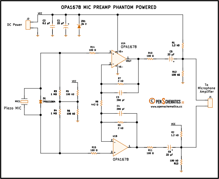
This circuit amplifies the signal from a piezoelectric microphone and draws its power directly from the phantom supply provided by mixing consoles and audio interfaces. It uses both amplifiers of the OPA1678 (U1A and U1B) in a symmetric mirror configuration: U1A delivers the in-phase signal and U1B the inverted signal, together forming a differential output.
The OPA1678 is a dual high-fidelity audio operational amplifier with very low distortion (THD+N of 0.00013 %), low noise (4.5 nV/√Hz) and a 10 MHz bandwidth. Its 4.5 to 36 V supply range and low quiescent current (1.6 mA per channel) make it ideal for phantom-powered circuits.
How it works
Power supply from phantom power
The phantom voltage arrives through connector J1. Zener diode ZD1 (24 V) acts as a protection clamp: it sets the maximum voltage that can reach the OPA1678 so its absolute maximum supply is never exceeded, but it does not regulate the voltage (below 24 V the zener does not conduct and the chip runs on whatever voltage is available). Capacitor C2 (0.1 µF) decouples the supply, and C1 (22 µF) provides current reserve for audio signal peaks. Resistors R1 and R2 (1.2 kΩ each) limit the current drawn from the phantom line, following the standard balanced phantom power scheme.
Non-inverted branch (U1A)
Piezoelectric microphone MIC1 is connected to the inverting input of U1A through a coupling network. Capacitor C5 (22 µF) blocks the DC component. Resistors R3 and R4 (1 MΩ each) provide bias for the piezoelectric capsule and define the input impedance, which must be high to preserve the transducer’s low-frequency response.
Diode D1 (TPD1E1B04) protects the amplifier input against electrostatic discharge (ESD) that could arrive through the microphone cable.
Resistors R5 and R6 (100 kΩ each) form a divider that sets the bias point of the non-inverting input. Capacitor C3 (390 pF) is part of the frequency compensation network.
U1A runs in inverting configuration, with R14 as the input resistor and R7 as the feedback resistor. Its gain is:
The negative sign reflects the 180° phase shift introduced by this branch.
Inverted branch (U1B) — differential output
U1B is the mirror branch of U1A: it receives the same microphone signal (through its own coupling network) and uses the same inverting topology, but with the signal fed in the opposite sense. As a result, the U1B output is the exact inverse of the U1A output.
The two outputs (U1A and U1B) thus form a differential signal: the useful audio information is the difference between them, while any common noise (interference, phantom-supply noise) appears the same on both branches and cancels at the receiver. This scheme delivers twice the useful amplitude of a single-ended output and dramatically improves noise immunity over long cables.
Capacitors C3 and C4 (390 pF), placed in parallel with each branch’s gain resistors, set the amplifier’s bandwidth. It must be wide enough to keep a flat response across the whole audio band, but not so wide that high-frequency noise gets through or the stage loses stability: the piezoelectric microphone’s own capacitance, together with the cable, can encourage oscillation if the loop bandwidth is too high, and these capacitors constrain it to the useful range.
Output
The two branches feed output connector J2 in differential mode (one to the hot pin, the other to the cold pin), ready to be connected to a balanced input on a mixing console, audio interface or recorder.
Piezoelectric vs. dynamic microphone
| Feature | Piezoelectric | Dynamic |
|---|---|---|
| Output impedance | Very high (>1 MΩ) | Low (150–600 Ω) |
| Output signal | Very low | Low to medium |
| Frequency response | Extended, with resonant peak | Flatter |
| Typical application | Contact pickup on acoustic instruments | Voice, instruments at a distance |
The piezoelectric transducer requires a high input impedance (R3, R4 = 1 MΩ) to avoid losing bass. A generic low-impedance preamplifier would attenuate the transducer’s low frequencies.
ESD protection
Diode D1 (TPD1E1B04) is a TI ESD protector designed specifically for sensitive signal lines. It withstands ±8 kV contact and ±15 kV air discharges per IEC 61000-4-2, with a parasitic capacitance of only 0.5 pF that does not affect the audio signal.
Phantom power
The phantom supply is delivered through resistors R12 and R13 (100 kΩ each) on the mixer side, over the same conductors that carry the audio signal. This circuit draws the required current (a few mA) from that voltage through R1 and R2 (1.2 kΩ), clamps it with ZD1 (24 V) and filters it with C1 and C2.
The 24 V of the zener represents the maximum voltage that can appear on the OPA1678 supply, not a regulated value: if the phantom source delivers less voltage, or the drop across R1/R2 is high under load, the chip runs on less than 24 V and still works normally (its operating range is 4.5 to 36 V). ZD1’s role is simply to prevent the upper limit from ever being exceeded.
Applications
- Contact microphone for acoustic instruments. Pickup for guitar, violin, piano or percussion by attaching a piezoelectric transducer to the body of the instrument.
- Field microphone. Recording ambience, nature sounds or sound effects with an encapsulated piezoelectric element, powered directly by the recorder.
- Hydrophone. Piezoelectric hydrophones capture sound underwater; this preamplifier provides the input impedance and gain they require.
- Vibration sensor. In machinery diagnostics, piezoelectric elements pick up mechanical vibrations that this circuit amplifies for analysis.
- Sound art installations. Contact microphones distributed across surfaces (walls, glass, metal) individually amplified via phantom power.
References and further reading
- PDFOPA1678 datasheet
This is the main source this article was created from.
- WEB
- WEB