
Sequential 10-output counter with LEDs
CD4017
Pinout
| Pin | Function |
|---|---|
| Q0 | Decoded output 0. High during the first of the ten counts and low the rest of the time. |
| Q1 | Decoded output 1. High only during the second count. |
| Q2 | Decoded output 2. High only during the third count. |
| Q3 | Decoded output 3. High only during the fourth count. |
| Q4 | Decoded output 4. High only during the fifth count. |
| Q5 | Decoded output 5. High only during the sixth count. |
| Q6 | Decoded output 6. High only during the seventh count. |
| Q7 | Decoded output 7. High only during the eighth count. |
| Q8 | Decoded output 8. High only during the ninth count. |
| Q9 | Decoded output 9. High only during the tenth count. |
| Cout | Carry output. Completes one cycle every ten clock pulses (high on counts 0–4, low on 5–9), meant for cascading several CD4017s and dividing the input frequency by ten. |
| CLK | Clock input with a built-in Schmitt trigger. The counter advances one step on each rising edge as long as CKEN is low. |
| CKEN | Clock Inhibit input. When low it lets the CLK edges advance the counter; when high it freezes the count and ignores any activity on CLK. |
| RESET | Asynchronous reset input. A high level immediately forces the count to 0 (Q0 high, all others low) without waiting for a clock edge. |
| VDD | Positive supply. Recommended range 3 V to 18 V. |
| VSS | Ground / negative supply reference. |
CD4017
The CD4017 is a CMOS decade counter from the 4000 series, made by Texas Instruments and by many other manufacturers. Inside it holds a 5-stage Johnson counter followed by a decoder that maps the count to ten independent outputs Q0–Q9: at any given moment only one of the ten is high, and it advances from Q0 to Q9 on each rising edge of the clock. After Q9 it loops back to Q0 and the cycle repeats.
It is a very forgiving chip: it runs on any supply between 3 V and 18 V, its clock input has a Schmitt trigger (it accepts slow and noisy signals without complaining), and its outputs can drive a small LED directly. All of that, together with the elegance of the “one output per count” idea, has made it the reference chip for light chasers, divide-by-N stages and teaching counters.
Package DIP-16 / SOIC-16 / TSSOP-16.
How the circuit works
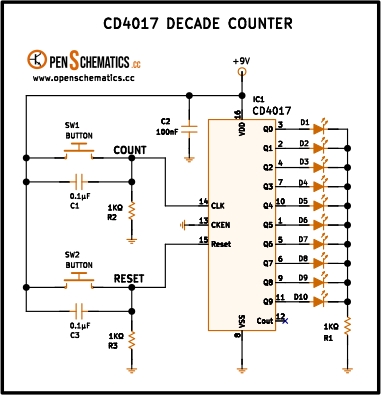
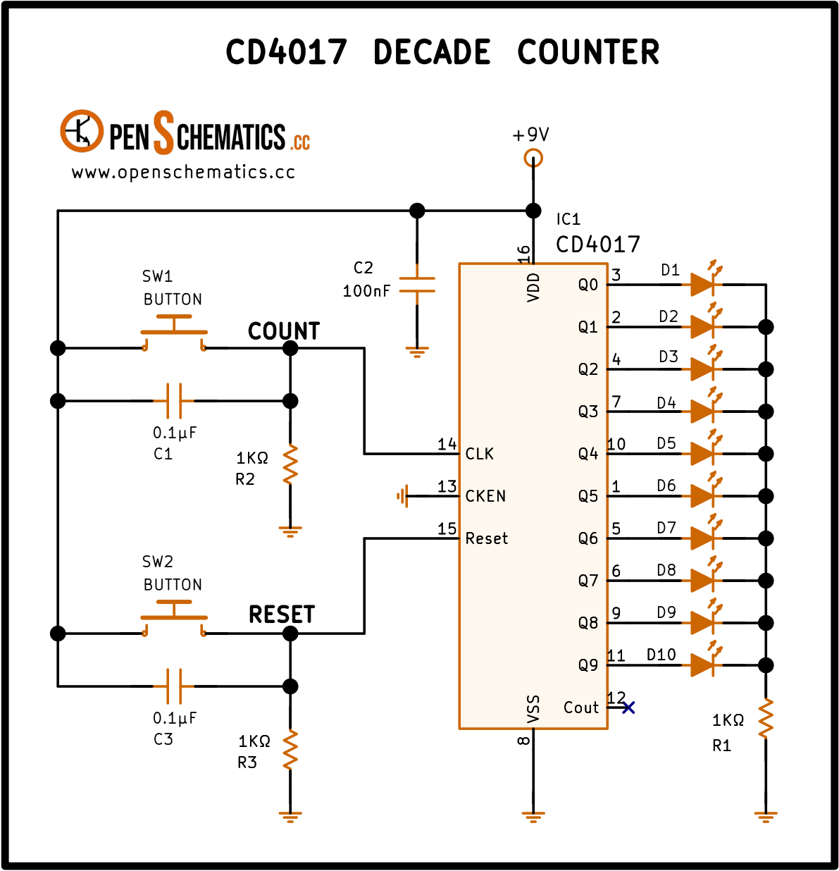
This build turns the CD4017 into a manual counter: every time you press SW1 the next LED in the row lights up, and SW2 clears everything and starts again from D1.
The count button (SW1). When pressed, the CLK input rises to +9 V and the CD4017 advances one step on the rising edge. When released, R2 (1 kΩ) pulls the clock line back to ground, ready for the next pulse. The small capacitor C1 (0.1 µF) forms a low-pass filter with R2 that absorbs the fast bounces of the mechanical contact and any switching sparks; without it, one press could easily register as several and skip LEDs. The Schmitt-trigger input built into the CD4017 clock pin finishes the job: it converts the softened rising edge from the filter into a clean digital transition.
The CKEN input. Pin 13 (Clock Inhibit) is tied permanently to ground so that clocking is always enabled. If it were pulled high, the counter would stop advancing even if pulses arrived on CLK.
The reset button (SW2). It works the same way as the count button, with its own debouncing R3 (1 kΩ) and C3 (0.1 µF), but attacking pin 15 (Reset). A high level on that input immediately forces the count to state 0: D1 (Q0) lights up and the other nine turn off, with no need to wait for a clock edge.
The ten outputs and the LEDs. Q0–Q9 are wired straight to the ten LEDs (D1–D10), which share a single 1 kΩ resistor (R1) to ground. Sharing is fine because the CD4017 only drives one output high at a time: two LEDs are never lit simultaneously, so the resistor always limits the current of a single LED.
The Cout output (pin 12). Left unconnected (the X in the schematic). Its job is to give one pulse every ten counts so several CD4017s can be cascaded to count past ten, which is not needed here.
Capacitor C2 (100 nF). The classic decoupling capacitor between VDD and VSS: it absorbs the current spikes that appear when the chip switches outputs and keeps noise from spreading down the supply line. Mount it as close as possible to pins 16 and 8 of the chip.
Application design
Pushbutton debounce
The small capacitor across the pull-down resistor forms a low-pass filter that smooths the spikes and sparks coming from the mechanical contact. The Schmitt trigger built into the CD4017 clock input finishes the cleanup and rejects any leftover bounces, so each press registers as a single edge.
LED current
With the shared 1 kΩ resistor R1 and a 9 V supply, the current through the active LED is approximately:
is the voltage lost inside the chip between and the output pin when that pin is high: it comes from the on-resistance of the output PMOS and grows with the current drawn. For the CD4017B, the datasheet guarantees a maximum drop of 0.5 V at 1.25 mA with ; at the 6 mA of this build the drop climbs to a bit over 1 V, which is the value used in the calculation. Enough for a 5 mm red LED to shine clearly.
Brightness can be raised by lowering R1, but it is best not to go past 10 mA per output: above that current grows quickly and the LED ends up dimmer than expected. When recalculating R1, use the new (larger at higher currents), not the one from this calculation.
Supply
The circuit runs on any voltage between 3 V and 18 V.
Changing the number of steps
To make the sequence roll over before reaching 10, connect the Qn+1 output (the one that would come after the last LED you want to use) to the RESET pin. Example: for a 7-step sequencer, wire Q7 (pin 6) directly to Reset (pin 15) and remove SW2 with its debounce; the instant Q7 tries to go high, the reset aborts it and forces the count back to Q0. It is the classic trick for building divide-by-N stages with the CD4017.
Other applications
The CD4017 has been in service for decades whenever something needs to be activated one at a time, in order and with simple control:
- Light chasers. LED strings, stage lighting and “Knight Rider” style effects with a CD4017 clocked by an NE555 astable.
- Divide-by-N stage. Wiring the Qn output to Reset gives a programmable divider between 2 and 10 with a single chip.
- Teaching counters. The classic example for teaching CMOS logic, pushbutton debouncing and output multiplexing without needing an oscilloscope.
- Small state machines. Fixed sequences of a few steps (drip irrigation controllers, teaching traffic lights, startup sequences) where each output enables a different stage.
- Pattern generators. Combining several outputs with diodes in OR you can generate repeating binary patterns without writing a line of code.
References and further reading
- WEB