
Stepper motor driver
A4988
Pinout
| Pin | Function |
|---|---|
| VBB1 / VBB2 | Motor power supply (8 to 35 V). This is the rail the coil currents are generated from, independent of the logic supply. |
| GND | Common power and logic ground. |
| VDD | Logic supply (3.3 to 5.5 V) for the control inputs and the internal translator. |
| OUT1A / OUT1B | Full-bridge outputs for motor coil 1. |
| OUT2A / OUT2B | Full-bridge outputs for motor coil 2. |
| SENSE1 / SENSE2 | Connection for the sense resistors (RS1 and RS2) the chip uses to measure each coil current and regulate it. |
| VREF | Reference voltage that sets the coil current limit. Its source is not shown in the schematic (see Application design). |
| STEP | Step clock input. Each rising edge advances the motor by one microstep. |
| DIR | Selects the direction of rotation. |
| MS1 / MS2 / MS3 | Select the microstepping resolution (full step, 1/2, 1/4, 1/8 or 1/16). |
| ENABLE | Enables the power outputs (active low). |
| RESET | Sends the translator to its home position and disables the outputs (active low). |
| SLEEP | Low-power mode; shuts down the internal regulators (active low). |
| ROSC | With resistor R2 it sets the current-regulation off-time and the decay mode. |
| CP1 / CP2 / VCP | Charge pump that generates the boosted voltage to drive the high-side MOSFETs. They carry external capacitors. |
| VREG | Internal regulator output for driving the low-side MOSFETs; decoupled with a ceramic capacitor. |
A4988
The A4988 is a driver for bipolar stepper motors with a built-in translator and PWM current regulation. Its big advantage is that it takes almost all of the load off the microcontroller: instead of having to switch the four half-bridges in the right sequence, you just give it one pulse on STEP per microstep and a level on DIR for the direction. The internal translator handles the rest.
It runs from a VBB motor supply of 8 to 35 V and a VDD logic supply of 3.3 to 5.5 V, and delivers up to 2 A per coil with adequate heat sinking. It offers microstepping down to 1/16 of a step, which smooths the motion and cuts the noise and resonances compared with full stepping. You will find it on almost any 3D printer or small CNC controller board.
How the circuit works
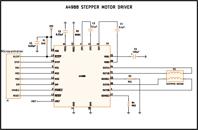
The circuit is the A4988’s typical application and reads in three blocks:
Control (left). A microcontroller generates the logic signals —STEP, DIR, ENABLE, RESET, SLEEP and the three microstepping-select lines MS1/MS2/MS3— that go into the A4988. Each edge on STEP advances the internal translator by one microstep; DIR sets the direction; MS1-MS3 pick the resolution (from full step down to 1/16).
Power and motor (right). The two motor coils of M1 connect to the two full-bridge outputs, OUT1A/OUT1B and OUT2A/OUT2B. The chip does not just apply voltage to the coils: it regulates their current. To do so it measures the drop across the sense resistors RS1 and RS2 (tied to SENSE1 and SENSE2) and, through PWM chopping, holds each current at the value the present microstep calls for. That value comes from an internal digital-to-analog converter stepping along a sine wave, so the two coils receive currents 90° out of phase and the rotor settles at intermediate points between the physical steps.
Internal services (top). The A4988 needs a charge pump (capacitors on CP1/CP2 and VCP) to generate the voltage that drives the high-side MOSFETs, and an internal regulator (VREG, with its decoupling ceramic) for the low-side ones. Resistor R2 on ROSC sets the off-time of the regulation PWM and the current decay mode. The motor supply is filtered with a 100 µF bulk capacitor (C5) plus a ceramic, essential for absorbing the current spikes the motor kicks back to the supply.
The one node the schematic leaves “hanging” is VREF: it shows up as a net label reaching the pin, but you cannot see where it comes from. That is exactly what the next section covers.
Application design
Current limit and sense resistors
The maximum current in each coil (the peak, at full scale) is set by VREF and the sense resistor :
Solving for the reference you need to apply for a target current:
With the usual sense resistors, a coil current of needs . The reference accepts roughly 0 to 2 V, so with the range reaches about ; it is best not to exceed the 2 A the IC can handle. Set just above your motor’s rated current, no more: the temperature of both the A4988 and the motor depends directly on that limit.
Where VREF comes from and what it should be
VREF is not a data signal: it is a DC reference voltage the A4988 uses as the full-scale value of its current DAC. It therefore has to meet three conditions:
- Stable and low-noise. Any variation in VREF maps directly onto a variation in motor current (and with it torque and temperature).
- Referenced to the driver’s ground (the same GND as the sense resistors), and well filtered with a small capacitor to ground.
- Within the 0-2 V range, never above VDD.
The usual ways to generate it, from simplest to most flexible:
- Resistive divider from a stable voltage. The most direct approach: two resistors from VDD (or better, from a clean reference) to ground, with the tap going to VREF. Simple, but the motor current is then “tied” to how stable that supply is.
- Adjustment trimmer. This is what commercial modules like the Pololu boards use: an adjustable divider that lets you set VREF with a screwdriver and measure it with a multimeter between the wiper and ground while calibrating the current. The practical option for prototypes.
- Precision reference + divider. When you want repeatability between units or stability over temperature, you start from a reference diode or IC instead of VDD.
- Filtered PWM output from the microcontroller. A PWM pin passed through an RC low-pass filter gives an adjustable DC voltage: it lets you change the current from firmware (for example, lowering it when the motor is idle so it does not heat up).
Power in the sense resistors
The resistors carry the coil current during the conduction phase, so they dissipate power:
At and that is , but at it is already : use resistors rated for at least (or two in parallel) with a low temperature coefficient, since their value goes straight into the current equation.
Power-up
Bring up VDD (logic) first and only then VBB (power), and place the bulk capacitor as close as possible to the VBB pins: the motor is an inductive load that kicks current spikes back on every switching event, and without that reservoir the power rail would ring and could shoot above the 35 V maximum.
Other applications
Beyond the single bipolar stepper motor control explained here, the A4988 and its application circuit show up in very similar setups:
- 3D printer and CNC electronics. Its flagship use: one A4988 per axis (X, Y, Z and extruder), plugged into sockets on the controller board.
- Positioning and automation axes. XY tables, focusing stages, dispensers or any mechanism that needs to move a known distance by counting steps, with no encoder.
- Robotics and home automation. Arms, platforms and leadscrew linear actuators where low-speed torque and open-loop positioning are what matter.
- Software current control. Using VREF from a filtered PWM, to cut consumption and heating at rest or to adapt the torque to the load.
References and further reading
- PDFA4988 datasheet
This is the main source this article was created from.
- WEB