
AC power meter
HLW8032
Pinout
| Pin | Function |
|---|---|
| Pin 1 (VDD) | Chip power supply. |
| Pin 2 (IP) | Positive input terminal for the differential current signal. Maximum effective differential input voltage ±30.9 mV. |
| Pin 3 (IN) | Negative input terminal for the differential current signal. Maximum effective differential input voltage ±30.9 mV. |
| Pin 4 (VP) | Positive input terminal of the voltage signal. Maximum effective input voltage ±495 mV. |
| Pin 5 (GND) | Chip ground. |
| Pin 6 (TX) | UART data output port. |
| Pin 7 (PF) | High-frequency rectangular pulse output with 50 % duty cycle. |
| Pin 8 (RX) | UART data input port (reserved, not intended to be used by the user). |
AC power meter with the HLW8032
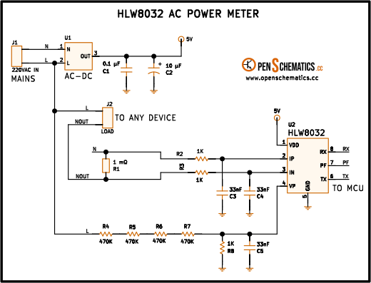
This circuit measures the voltage, current and power consumed by a load connected to the 220 V AC mains. It uses the HLW8032, a dedicated energy-metering IC that integrates two 24-bit sigma-delta ADCs, a digital multiplier and a UART output that delivers ready-to-read results to a microcontroller.
The HLW8032 is at the heart of many smart plugs and household energy monitors. With just a shunt resistor for the current channel, a resistive divider for the voltage channel and a few filter capacitors, it achieves active power measurement with a typical accuracy of ±2 %.
How it works
The circuit has three blocks: the power supply, the voltage channel and the current channel.
Power supply
An AC-DC module (U1) converts the 220 V AC mains into 5 V DC to power the HLW8032 and its associated microcontroller. Capacitors C1 (0.1 µF) and C2 (10 µF) decouple the IC supply.
Voltage channel (VP – GND)
Resistors R4, R5, R6 and R7 (470 kΩ each) form a resistive divider that scales the mains voltage down to a safe level for the HLW8032’s internal ADC. Using four 470 kΩ resistors in series distributes the voltage across them, which allows standard low-cost resistors rated for 200 V each. Capacitors C3 and C4 (33 nF each) filter high-frequency noise from the voltage signal.
The peak mains voltage (220 V × √2 ≈ 311 V) is divided among the four resistors. The fraction reaching the ADC is:
where is the sum of the four divider resistors and is the resistor on the ADC side.
Current channel (IP – IN)
Resistor R1 (1 mΩ) is a very low value shunt resistor placed in series with the load. The current flowing through the load produces a proportional voltage drop:
With R1 = 1 mΩ, a current of 10 A produces only 10 mV of drop, which minimises power dissipation in the shunt. The 24-bit ADC of the HLW8032 has enough resolution to measure this small signal accurately.
Internal processing
The HLW8032 samples both channels simultaneously, computes the RMS values of voltage and current, and multiplies them to obtain active power. Results are sent through the UART output (TX, pin 6) in 24-byte frames at 4800 bps. The PF pin outputs a pulse for each energy quantum, useful for integrating total consumption (kWh).
Voltage divider resistors
Four 470 kΩ resistors are used instead of a single high-value resistor for two reasons:
| Aspect | One resistor | Four resistors |
|---|---|---|
| Voltage per resistor | 311 V peak | ~78 V peak |
| Resistor type | High voltage (expensive) | Standard (cheap) |
| Dissipation | Concentrated | Distributed |
Standard 470 kΩ resistors (1206 or axial) are rated for 200 V, well above the ~78 V each one sees.
Shunt resistor R1
The choice of R1 determines the current range and resolution:
| R1 | Maximum current | Drop at maximum current |
|---|---|---|
| 1 mΩ | 30 A | 30 mV |
| 2 mΩ | 15 A | 30 mV |
| 5 mΩ | 6 A | 30 mV |
A lower resistance allows higher current measurement, but the signal is smaller and more susceptible to noise. The 1 mΩ value in this schematic supports loads up to 30 A (6.6 kW at 220 V).
UART communication
The HLW8032 transmits automatically on TX at 4800 bps, 8N1. Each frame contains:
- Voltage coefficient and voltage register
- Current coefficient and current register
- Power coefficient and power register
- Verification checksum
The microcontroller computes the actual values by dividing the coefficient by the register:
Resistors R2, R3 and R8 (1 kΩ) protect the TX, RX and PF lines against overvoltage.
Safety
This circuit operates at mains voltage (220 V AC), which is potentially lethal. The resistive divider and shunt are directly connected to the mains. The entire high-voltage section must be on an isolated PCB inside a sealed enclosure. Never touch any component while the circuit is plugged in.
Applications
- Smart plug. An ESP8266 or ESP32 reads the HLW8032 data via UART and publishes it over WiFi, allowing consumption monitoring from a phone.
- Household energy meter. Installed in the distribution board, it measures the power consumed by an entire household circuit.
- Appliance protection. If the power or current exceeds a threshold, the microcontroller activates a relay to disconnect the load.
- Industrial energy analysis. Combined with a data logger, it allows studying the consumption profile of a machine over time.
- Home automation. Integrated into systems such as Home Assistant or Tasmota to automate switching devices on and off based on their actual consumption.
References and further reading
- PDFHLW8032 datasheet
This is the main source this article was created from.
- WEB
- WEB