
Single-digit counter with 7-segment display
CD4026
Pinout
| Pin | Function |
|---|---|
| CLK | Clock input. The count advances on each rising edge. |
| CI | Clock Inhibit input. A high level freezes the count. |
| DEI | Display Enable Input. A low level blanks the seven segment outputs. |
| DEO | Display Enable Output. Used for cascading stages and suppressing leading zeros. |
| Cout | Carry output. One pulse every ten counts, for cascading decades. |
| a | Output for the top horizontal segment. |
| b | Output for the upper-right vertical segment. |
| c | Output for the lower-right vertical segment. |
| d | Output for the bottom horizontal segment. |
| e | Output for the lower-left vertical segment. |
| f | Output for the upper-left vertical segment. |
| g | Output for the middle horizontal segment. |
| UCS | Copy of the c segment that ignores DEI, to keep a pilot indicator visible when the rest of the digit is blanked. |
| RESET | Asynchronous reset. A high level forces the count to digit 0 at once. |
| VDD | Positive supply. Range 3 V to 18 V. |
| VSS | Ground. |
CD4026
The CD4026 is a CMOS decade counter with a built-in seven-segment decoder, from the 4000 series, made by Texas Instruments and others. It packs into a single chip two blocks that usually come separately: a counter that advances from 0 to 9 on each rising clock edge, and a decoder that translates that count into the seven outputs a–g ready to drive a common-cathode seven-segment display directly.
It runs on any supply between 3 V and 18 V, the clock input accepts slow or noisy signals thanks to its built-in Schmitt trigger, and the segment outputs can drive the display LEDs directly as long as the current per segment is kept low.
Package DIP-16 / SOIC-16 / TSSOP-16.
How the circuit works
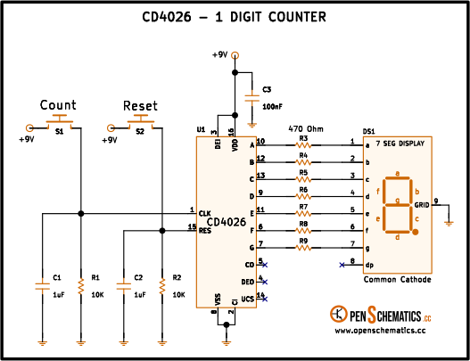
This build turns the CD4026 into a manual single-digit counter: every time you press the Count button, the number shown on the display goes up by one, from 0 to 9, and the Reset button brings it back to 0.
The Count button (S1). When pressed, the CLK input rises to +9 V and the CD4026 advances one step on the rising edge. When released, R1 (10 kΩ) pulls the clock line back to ground, ready for the next pulse. Capacitor C1 (1 µF) forms a low-pass filter with R1 that absorbs the fast bounces of the mechanical contact and switching sparks; without it, one press could easily register as several and the digit would skip numbers. The Schmitt trigger built into the CD4026 clock input finishes the job: it converts the softened rising edge from the filter into a clean digital transition.
The Reset button (S2). It works the same way as the count button, with its own debouncing R2 (10 kΩ) and C2 (1 µF), but attacking pin 15 (Reset). A high level on that input immediately forces the count back to digit 0, with no need to wait for a clock edge.
The CI input. Pin 2 (Clock Inhibit) is tied permanently to ground together with VSS so that clocking is always enabled. If it were pulled high, the counter would stop advancing even if pulses arrived on CLK.
The DEI input. Pin 3 (Display Enable Input) is tied to VDD so the seven segment outputs are always active and the digit is visible at all times. If it were pulled low, the seven outputs would go to zero and the display would blank completely, although the counter would keep advancing internally.
The seven current-limiting resistors (R3–R9, 470 Ω). Each segment output has its own resistor in series with the corresponding display LED. Unlike a counter that lights one LED at a time, here several segments are almost always lit at once (the digit 8 lights all seven), and a shared resistor would split the current between segments, making the digit brightness change from number to number.
Display DS1. A common-cathode seven-segment display: all seven LEDs share their negative terminal, which is taken to ground through the GRID pin. The CD4026 drives high the segments that make up each digit and R3–R9 limit their current.
The unused outputs (Cout, DEO, UCS). The three outputs in the lower right corner of the CD4026 are left floating (the X marks in the schematic). Cout (pin 5) would give one pulse every ten counts for cascading more digits, DEO (pin 4) would be used for blanking in a cascade, and UCS (pin 14) would output the c segment ignoring DEI so a pilot could stay lit while the rest of the digit is blanked. None of those is useful in a single-digit build with the display always on.
Capacitor C3 (100 nF). The decoupling capacitor between VDD and VSS: it absorbs the current spikes that appear when the chip switches segments and keeps noise from spreading down the supply line. Mount it as close as possible to pins 16 and 8 of the chip.
Application design
Pushbutton debounce
The time constant of the R–C filter is:
Of the same order as the typical bounces of a pushbutton, enough for the Schmitt trigger at the clock input to see a single clean edge per press. The same applies to the Reset button through R2 and C2.
Current per segment
With R3–R9 of 470 Ω and a 9 V supply, the current through each lit segment is approximately:
is the drop inside the chip between and the output pin when it is high. For the CD4026B at 10 V the datasheet guarantees a maximum of 0.5 V at 1.6 mA; at the 14 mA of this build it grows, and the real current through each LED ends up a bit below the calculated value. Enough for the segments to shine clearly.
With the digit 8 lit the chip delivers around 100 mA total — a high regime but within what the CD4026 handles. If the display needs more brightness, drop R closer to the absolute per-pin limit given by the datasheet, or add a per-segment buffer (transistors or a ULN2003).
Supply and scalability
The circuit runs on any voltage between 3 V and 18 V; when changing the supply, adjust R3–R9 to keep a similar brightness without overdriving the outputs.
To count beyond 9, connect the Cout output (pin 5) to the CLK input of the next CD4026 stage, with its own display and resistors, and share the Reset line. To roll over before reaching 9 the most direct way is to decode the target digit with external logic on the segment outputs and feed it back to Reset.
Other applications
The CD4026 has been in service since the seventies whenever a count needs to be shown on a seven-segment display without reaching for a microcontroller:
- Event counters. Counting button presses, wheel turns, items on a conveyor belt or finished parts, with as many decade stages chained as digits are needed.
- Discrete clocks and stopwatches. Before cheap microcontrollers, desktop digital clocks were built from a chain of CD4026s (or the sibling CD4033) fed by a mains divider or a 32.768 kHz crystal.
- Teaching frequency meters. Counting pulses during a fixed one-second window gives a direct frequency reading in Hz.
- Divide-by-N stages with a visible count. Cout gives one pulse every ten counts and works both to chain digits and to divide a signal by 10 while the count is visible on the display.
- Scoreboards. In electronic board games, homebrew pinballs or educational projects, where a large display is wanted and there is nothing to program.
References and further reading
- WEB
- WEB