
Balanced line driver for XLR output
INA1650
Pinout
| Pin | Function |
|---|---|
| Pin 1 (IN+_A) | Non-inverting input of channel A. |
| Pin 2 (COM_A) | Internal common node of channel A (precision resistor network). |
| Pin 3 (IN−_A) | Inverting input of channel A. |
| Pin 4 (IN−_B) | Inverting input of channel B. |
| Pin 5 (COM_B) | Internal common node of channel B. |
| Pin 6 (IN+_B) | Non-inverting input of channel B. |
| Pin 7 (OUT_B) | Channel B output. |
| Pin 8 (REF_B) | Channel B reference. Sets the quiescent voltage of OUT_B. |
| Pin 9 (VMID(OUT)) | Internal mid-point output. |
| Pin 10 (VMID(IN)) | Mid-point input. Sets the common reference for both branches. |
| Pin 11 (REF_A) | Channel A reference. Sets the quiescent voltage of OUT_A. |
| Pin 12 (OUT_A) | Channel A output. |
| Pin 13 (VEE) | Negative supply. |
| Pin 14 (VCC) | Positive supply. |
Balanced line driver for XLR output with the INA1650
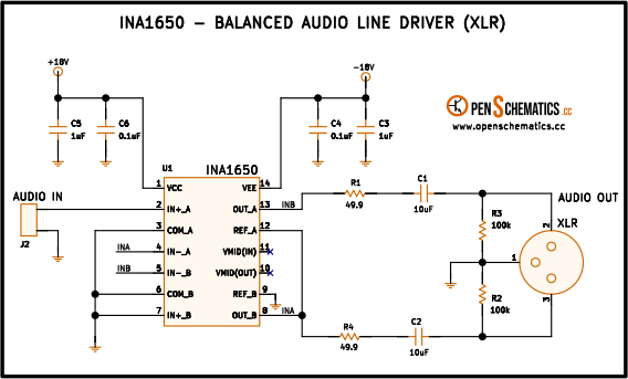
This circuit converts an unbalanced audio signal (for example, the output of a line stage or a DAC) into a balanced signal suitable for long-cable transmission to a mixing console, PA amplifier or studio stage over an XLR connector. The conversion is performed by a single IC, the INA1650, which integrates both branches of the differential driver, the precision matched resistors and the input filters.
The INA1650 is a Texas Instruments IC designed specifically for professional audio: 0.0002 % THD+N, 8 nV/√Hz noise and typical common-mode rejection ratio (CMRR) of 90 dB thanks to the on-chip laser-trimmed resistors. Although marketed as a balanced-line receiver, its symmetric topology also allows it to be used as a balanced driver, taking advantage of the same resistor matching to deliver two equal, opposite-phase outputs with a precision hard to achieve with discrete components.
How it works
Dual ±18 V supply
The circuit runs on symmetric +18 V and −18 V rails, close to the INA1650 maximum of ±18 V, which maximises the output dynamic range. Each rail carries local decoupling in three stages:
- C1 and C2 (10 µF) provide energy reserve for audio-signal transients and decouple the DC component of the rails, so that the signal on the XLR output stays balanced with 0 V DC.
- C3 and C5 (1 µF) are intermediate low-ESR decoupling capacitors that cover the frequency range between the large electrolytics and the small ceramics.
- C4 and C6 (0.1 µF) filter high frequencies right next to the IC supply pins.
This staged decoupling scheme is the recommended one for low-noise audio amplifiers: the 10 µF caps absorb slow variations and the 0.1 µF caps short RF noise on the rails to ground.
Integrated EMI/RFI filters
The INA1650 includes low-pass filters on each differential input, tuned to attenuate radio signals (AM, FM, cellular) that couple onto the balanced cable by antenna effect. This eliminates the classic “radio station bleeding into the audio” problem in stages near communication antennas, without adding external ferrites or filters.
Differential core (INA1650)
Inside the INA1650 there are two operational amplifiers and a resistor network matched to 0.005 %. In this driver configuration:
- One branch delivers the in-phase signal at OUT_A (pin 12).
- The other branch delivers the 180°-inverted signal at OUT_B (pin 7).
Equal amplitude between both branches is what gives the differential pair its ability to reject interference: any noise picked up by the balanced cable (AM radio, 50 Hz mains hum, nearby transformers) appears in common mode on both conductors and cancels out at the receiver. Internal resistor matching is the key to high CMRR, unreachable with any discrete build using 1 % tolerances.
XLR output
The output goes to connector J1 (XLR, three pins):
- Pin 1: ground (cable shield).
- Pin 2: HOT — in-phase signal, connected to OUT_A through R4 (49.9 Ω).
- Pin 3: COLD — inverted signal, connected to OUT_B through R1 (49.9 Ω).
Series resistors R1 and R4 (49.9 Ω each) give the XLR output its characteristic impedance, which must match the impedance of the balanced audio cable (typically 100 Ω between the two conductors) to avoid reflections and ensure clean signal transmission.
Balanced vs. unbalanced
| Feature | Unbalanced (RCA, jack) | Balanced (XLR, TRS) |
|---|---|---|
| Signal conductors | 1 + ground | 2 + ground |
| Interference rejection | Low | High (via common-mode cancellation) |
| Typical maximum length | 3–5 m | 30 m or more |
| Applications | Home Hi-Fi | Studio, live sound, PA |
Applications
- Balanced output for players and DACs. Convert the unbalanced output of a DAC, CD player or audio interface into a balanced XLR feed for a studio console or PA amplifier without picking up mains hum along the cable.
- Active DI boxes. Basis for a powered Direct Injection box that balances an electric instrument signal (guitar, keyboard, bass) and sends it to the mixer over a long balanced cable.
- Professional audio-card outputs. Final stage of an audio interface or processor delivering the signal to active monitors or stage snakes.
- Signal isolation between equipment. Sending balanced audio between racks with different ground references, avoiding ground loops and 50 Hz hum.
- Audio distribution in TV or radio studios. Long cabling between control room, set and central control, where the high CMRR of the INA1650 keeps the signal clean against lighting and camera interference.
References and further reading
- PDFINA1650 datasheet
This is the main source this article was created from.
- WEB
- WEB
- WEB