
5-LED VU meter
KA2284
Pinout
| Pin | Function |
|---|---|
| Pin 1 (OUT1) | Current output for the first LED, −10 dB threshold (lowest on the scale). |
| Pin 2 (OUT2) | Current output for the second LED, −5 dB threshold. |
| Pin 3 (OUT3) | Current output for the third LED, 0 dB threshold (reference). |
| Pin 4 (OUT4) | Current output for the fourth LED, +3 dB threshold. |
| Pin 5 (GND) | Supply ground and reference of the internal dividers. |
| Pin 6 (OUT5) | Current output for the fifth LED, +6 dB threshold (full scale). |
| Pin 7 (OUT) | Output of the internal rectifier and envelope detector. A capacitor and a resistor to ground set the attack and decay time. |
| Pin 8 (IN) | AC-coupled signal input to the internal amplifier and rectifier. |
| Pin 9 (VCC) | Positive supply (typically 3.5 V to 16 V). |
KA2284
The KA2284 displays the level of an audio signal on a five-LED bargraph. It integrates an AC-detection amplifier (Gv = 26 dB), an envelope detector and five comparators with fixed thresholds at −10, −5, 0, +3 and +6 dB. Each output is a constant-current source of 15 mA that on its own sets the current through its LED.
It runs from a single 3.5 V to 16 V supply and packs the whole scheme into a 9-pin SIP package. It is the classic building block for adding a visual level indicator to amplifiers, mixers or recorder input stages.
How it works
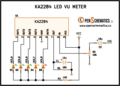
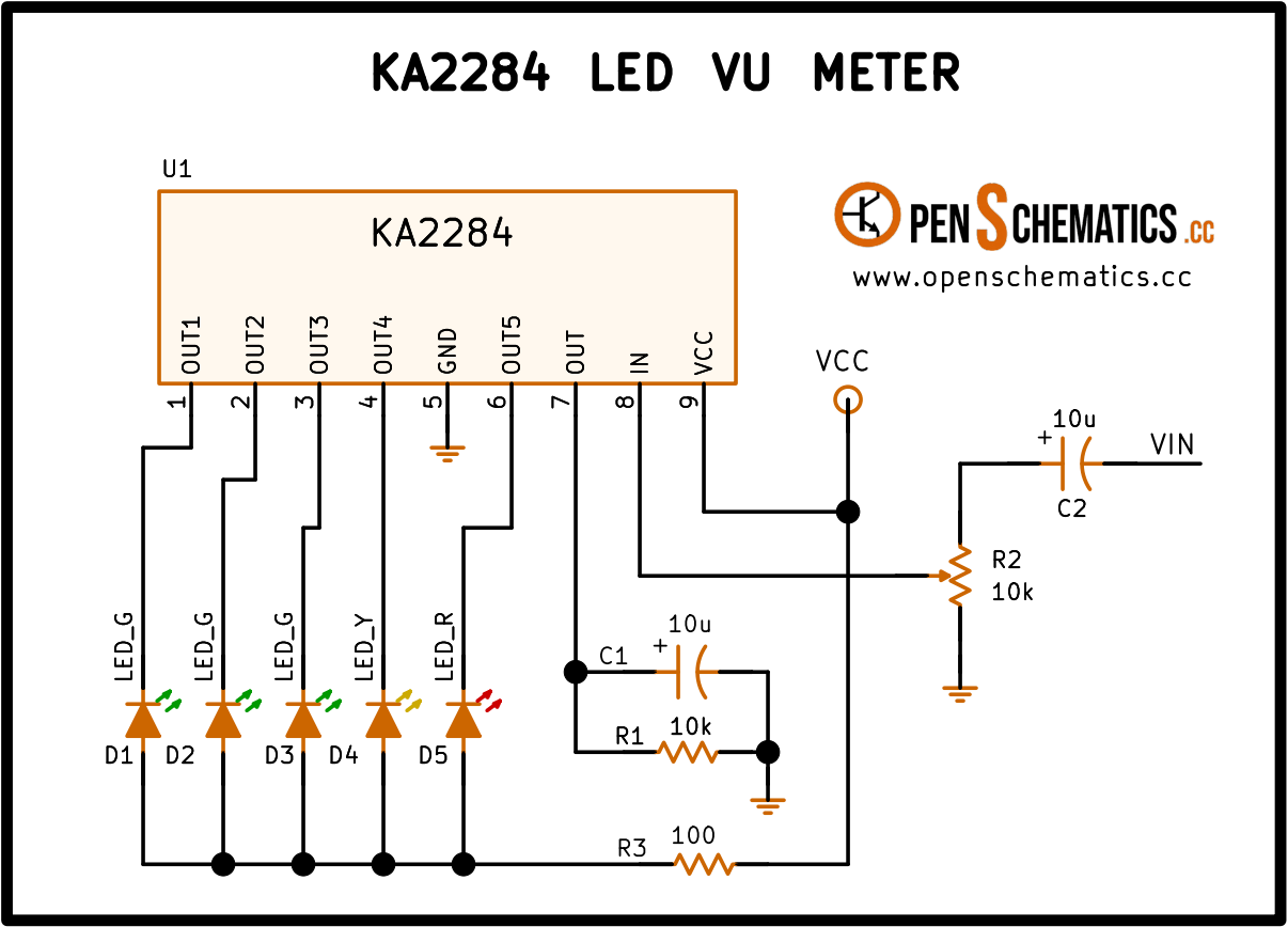
The signal enters pin 8 through C2 (10 µF), which blocks DC. Potentiometer R2 (10 kΩ) is an adjustable divider that trims the sensitivity to match the source level.
Inside the IC the signal is amplified and rectified. The resulting voltage appears at pin 7, where C1 (10 µF) and R1 (10 kΩ) filter the ripple and set the detector time constant. The five internal comparators drive OUT1 to OUT5 in a cumulative fashion: the higher the level, the more LEDs on.
R3 (100 Ω) in the common cathode return caps the total current when all LEDs light at once. D1–D3 are green, D4 yellow and D5 red, following the classic VU meter convention.
Application design
Time constant
C1 and R1 at pin 7 set how fast the bargraph rises and falls:
With and that gives , a common compromise between following transients and not flickering between beats.
Current and supply
With all LEDs on at 15 mA each, total current reaches about 75 mA. The drop across R3 = 100 Ω rises to 7.5 V, so the supply should be at least 9–10 V to leave headroom for the outputs and the LEDs. At lower voltages, R3 must drop to 47 Ω or be shorted out, since the IC itself already sets the per-LED current.
Other applications
Beyond the classic VU meter, the KA2284 works as a level indicator for any slowly-varying signal:
- VU meter for amplifiers and mixers. The original use.
- Recording-level indicator. Warns when the signal approaches clipping at the input of a recorder or audio interface.
- Battery-charge indicator. With a divider at the input, it shows battery state at a glance.
- Light-intensity meter. A photodiode or LDR with proper conditioning drives the input for a simple visual lux meter.
- Vibration or noise-level indicator. With an electret microphone and preamplifier it turns into a qualitative sound meter.
References and further reading
- PDFKA2284 datasheet
This is the main source this article was created from.
- WEB
- WEB