
Astable multivibrator with transistors
2N3904

Pinout
| Pin | Function |
|---|---|
| E (emitter) | Terminal through which the main current leaves the NPN transistor. In normal operation it sits at a lower voltage than the base and the collector. |
| B (base) | Control terminal. The small current injected into the base governs the much larger current flowing between collector and emitter (2N3904 typical hFE of 100 to 300). |
| C (collector) | Terminal through which the main current enters when the transistor conducts. It is biased above the emitter through the load. |
2N3904
The 2N3904 is a general-purpose NPN bipolar transistor, one of the most common parts in electronics. It comes in a small three-legged plastic package (TO-92) and behaves like a controlled switch: a very small current into its middle pin (the base) allows a much larger current to flow between the other two (collector and emitter).
This circuit uses two identical transistors (Q1 and Q2) wired in a cross-coupled way. Any other small NPN transistor (BC547, 2N2222…) works just as well.
How the circuit works
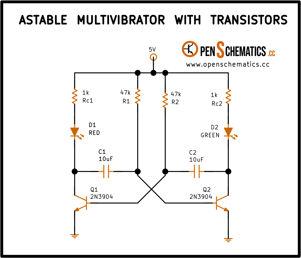
The circuit is an astable multivibrator: it never stays still. The two transistors take turns switching on and off, and they drag the LEDs with them: when D1 (red) is on, D2 (green) is off, and vice versa.
The trick is in the cross-wiring. Look at the schematic: the collector of Q1 connects, through capacitor C1, to the base of Q2; and the other way around, the collector of Q2 reaches the base of Q1 through C2. Each transistor is “watching” the other.
How they take turns. Say Q1 has just switched on (saturated):
- The collector of Q1 drops to almost 0 V. Current starts flowing through Rc1 and LED D1, which lights up.
- That sudden drop travels through C1 down to the base of Q2 and pushes it low. Q2 switches off, and LED D2 goes dark with it.
- Now C1 slowly charges up through R2, and the base of Q2 rises little by little.
- When the base of Q2 reaches 0.7 V (the magic voltage that turns on any NPN transistor), Q2 snaps on.
- As Q2 switches on, it does the same trick to Q1 in reverse: it pulls Q1 off through C2. The roles swap.
This cycle repeats forever, and the two LEDs blink alternately.
Who starts the party? In theory both transistors are in perfect balance and neither one should switch on first. In practice no two transistors are exactly the same: one turns on a fraction of a millisecond before the other, and that is enough to kick the circuit into oscillation the moment you connect the supply.
Application design
Blink rate
The blink rate is set by how long each capacitor (C1 or C2) takes to charge through its resistor (R2 or R1). Bigger R or bigger C means slower blinking. The formula is:
With the schematic values ( and ):
That is a bit more than one blink per second, a comfortable rate for the eye.
Changing the rate
To speed the blink up or slow it down, change R or C in both branches at the same time (so they stay matched):
- With the blink gets so fast it almost looks steady (about 15 Hz).
- With it turns into one flash every 6 or 7 seconds.
Uneven blink
If you make R1 different from R2 (or C1 different from C2), each LED will stay lit for a different length of time. You can use this to get effects like “short flash, long pause”.
Supply
The ideal supply for this build is 5 V: at that voltage the LEDs shine nicely, the transistors work well within their limits, and the resistor values in the schematic (1 kΩ and 47 kΩ) are sized for that case.
A higher voltage can be used, but then two things must be done: add a protection diode between the base and emitter of each transistor (the 2N3904 cannot handle more than 6 V in reverse across that junction, and on every switching event the base is pulled down to roughly ), and recalculate the resistors so neither the LEDs nor the transistors are pushed past their current limits.
Other applications
The transistor astable multivibrator is a textbook circuit, but it is still handy:
- Blinking lights. Bicycle beacons, toys, indicators… whenever a microcontroller or a 555 timer would be overkill.
- Slow clock. As a pulse source for simple digital counters.
- Buzzer or siren. With smaller capacitors (nF instead of µF), the frequency rises into the audible range and can drive a small speaker or a piezo directly.
- Home-made square-wave generator. For testing filters and other circuits without needing a proper signal generator.
- Learning circuit. One of the best examples for understanding how a transistor switches on and off without any expensive instruments.