
Dual LED blinker with PNP astable multivibrator
2N3906
Pinout
| Pin | Function |
|---|---|
| E (emitter) | Terminal through which the main current enters the PNP transistor. In normal operation it sits at a higher voltage than the base and the collector. |
| B (base) | Control terminal. The small current flowing out of the base governs the much larger current between emitter and collector (2N3906 typical hFE of 100 to 300). |
| C (collector) | Terminal through which the main current leaves when the transistor conducts. It is biased below the emitter through the load. |
2N3906
The 2N3906 is a general-purpose PNP bipolar transistor, the classic counterpart to the 2N3904. It shares the same TO-92 package and pinout, but being PNP it works “the other way around”: the emitter sits at the top (tied to the positive supply) and to turn it on you have to pull the base down instead of pushing it up.
This circuit uses two identical transistors (Q1 and Q2) wired cross-coupled. Any other small PNP (BC557, 2N2907…) plays the same role.
How the circuit works
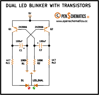
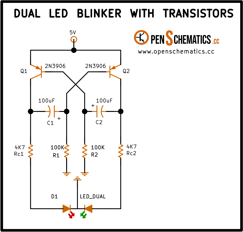
The circuit is an astable multivibrator: it never stops. The two PNP transistors take turns switching on and off, and on each swap they change which half of the common-cathode bicolor LED is being driven. The result is a single LED that blinks, alternating between red and green.
One LED, two colours. D1 is a single package with two chips inside sharing a common cathode. Rc1 drives the red anode from the collector of Q1, and Rc2 drives the green anode from the collector of Q2. Since only one transistor is on at any time, only one colour is visible at any time.
The trick is in the cross-wiring. As in any astable, the collector of Q1 connects through capacitor C1 to the base of Q2; and the collector of Q2 reaches the base of Q1 through C2. Each transistor is “watching” the other.
How they take turns. Say Q1 has just switched on:
- Q1 conducts between emitter and collector, so its collector jumps up to almost 5 V. Current flows through Rc1 and through the red chip of the LED, which lights up.
- That sudden rise on Q1’s collector travels through C1 up to the base of Q2 and pushes it high. On a PNP, pulling the base above the emitter turns it off, so Q2 stops conducting and the green chip goes dark.
- Now C1 slowly discharges through R2 towards ground, and the base of Q2 drifts down.
- When the base of Q2 gets about 0.7 V below the emitter (the magic voltage that turns on any PNP transistor), Q2 snaps on.
- As Q2 switches on, it does the same trick to Q1 in reverse: it pulls Q1 off through C2. The roles swap, and now the other colour is lit.
This cycle repeats forever, and the bicolor LED keeps alternating colours.
Who starts the party? In theory both transistors are perfectly balanced and neither one should switch on first. In practice no two transistors are exactly the same: one turns on a fraction of a millisecond before the other, and that is enough to kick the circuit into oscillation the moment you connect the supply.
Application design
Blink rate
Just as in the NPN version, the rate is set by how long each capacitor (C1 or C2) takes to discharge through its matching resistor (R2 or R1). Bigger R or bigger C means slower blinking. The formula is:
With the schematic values ( and ):
That is one full cycle every 14 seconds: roughly 7 seconds red, then 7 seconds green. A slow, steady pace, well suited to a visual indicator that catches the eye without being irritating.
It may look surprising that gives such a long time when we “only” need to reach 0.7 V. The catch is that the capacitor does not start at 0 V: on every switching event its voltage snaps to about , and it has to climb from there until it crosses 0.7 V. It is that full swing that produces the well-known factor in the formula.
Changing the rate
To speed the blink up or slow it down, change R or C in both branches at the same time (so they stay matched):
- With each cycle takes a bit over a second, a well-visible blink.
- With the colour switches about 7 times per second, close to the point where the eye starts to blend both colours into an amber tint.
Red anode vs green anode
In a typical bicolor LED the red and green chips do not share the same forward voltage () or the same brightness at the same current. With 4.7 kΩ for Rc1 and Rc2 the current lands around per branch, a gentle level meant to make both colours visible without one overpowering the other.
If one colour looks noticeably dimmer than the other, tune its Rc alone (a smaller resistor gives a brighter chip). Rc1 and Rc2 need not stay equal: Rc1 only sets the red current and Rc2 only sets the green current.
Supply
The intended supply for this build is 5 V. Higher voltages still work, but two things must be kept in mind: add a protection diode between the base and emitter of each transistor (the 2N3906 cannot take more than 5 V in reverse on that junction, and on every switching event the base is pushed up to roughly above the emitter), and recalculate Rc1 and Rc2 so the LED chips are not driven past their rated current.
Other applications
The PNP astable with a bicolor LED is a textbook circuit that still has its place:
- Two-state visual alert. A red/green LED grabs more attention than a single blinking one, and it only takes up one hole in the panel.
- “Alive” simulator. In model trains, toy robots or costumes, a slow colour change suggests that “something is happening” inside the device.
- Slow clock. As a pulse source for simple digital counters when precision does not matter.
- Home-made square-wave generator. The collector of either transistor swings cleanly between 0 V and 5 V.
- Learning circuit. One of the best examples for understanding how a PNP transistor switches on and off, and how a signal is coupled by a capacitor from one collector to the opposite base.