
Mono audio amplifier
LM386
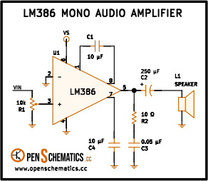
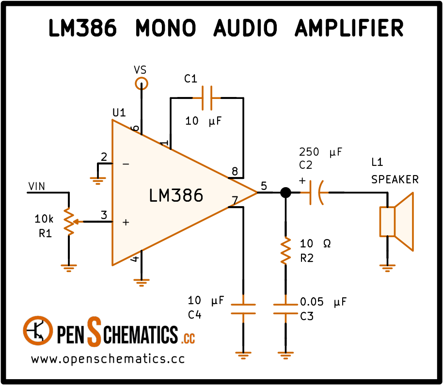
Pinout
| Pin | Function |
|---|---|
| Pin 1 (Gain) | Gain control. Connected to C1 (10 µF) toward pin 8 to set the gain to 200 (46 dB). |
| Pin 2 (−IN) | Inverting input. Tied to ground to configure the amplifier in non-inverting mode. |
| Pin 3 (+IN) | Non-inverting input. Receives the audio signal through R1 (10 kΩ), which acts as the input resistor. |
| Pin 4 (GND) | Supply ground. |
| Pin 5 (OUT) | Power output. Connected to the speaker through C2 (250 µF) and with R2 (10 Ω) as a damping network. |
| Pin 6 (VS) | Positive supply (4 to 12 V). |
| Pin 7 (Bypass) | Internal midpoint decoupling. A capacitor to ground can be added to improve supply rejection. |
| Pin 8 (Gain) | Gain control. Connected to C1 (10 µF) from pin 1 to increase the gain from 20 to 200. |
Mono audio amplifier with the LM386
This circuit amplifies a low-level audio signal to drive an 8 Ω speaker with up to 700 mW of power. It uses a single integrated circuit (the LM386), two capacitors and two resistors: the simplest audio amplifier you can build with a dedicated IC and a handful of passive components.
The LM386 is an audio power amplifier designed to operate from low supply voltages (4 to 12 V) while drawing very little quiescent current (about 4 mA). It has internal feedback resistors that set a default gain of 20 (26 dB), and allows raising it to 200 (46 dB) with a single external capacitor between pins 1 and 8.
How it works
The audio signal enters the non-inverting input (pin 3) through resistor R1 (10 kΩ), which limits the input current and sets the impedance seen by the signal source. The inverting input (pin 2) is tied directly to ground, configuring the amplifier in non-inverting mode.
Capacitor C1 (10 µF) between pins 1 and 8 shorts out the internal 1.35 kΩ resistor at audio frequencies, raising the gain from 20 to 200. At very low frequencies the capacitor presents a high impedance and the gain rolls off, providing a natural high-pass filter that rejects DC and unwanted sub-bass content.
The output (pin 5) drives the speaker through coupling capacitor C2 (250 µF). This capacitor blocks the DC component of the output (which is biased at half the supply voltage) and passes only the AC audio signal. Resistor R2 (10 Ω) forms a damping (Zobel) network that stabilises the amplifier against inductive loads and prevents high-frequency oscillation.
Gain
The gain of the LM386 is controlled by what is connected between pins 1 and 8:
| Connection between pins 1 and 8 | Gain | Gain (dB) |
|---|---|---|
| Nothing (open circuit) | 20 | 26 |
| 10 µF capacitor | 200 | 46 |
| Resistor + capacitor in series | 20 to 200 | 26 to 46 |
A resistor in series with the capacitor lets you set any intermediate gain value. For example, a 1.2 kΩ resistor in series with 10 µF gives a gain of approximately 50.
Coupling capacitor C2
The value of C2 sets the low-frequency cut-off of the amplifier together with the speaker impedance:
With C2 = 250 µF and an 8 Ω speaker the cut-off frequency is about 80 Hz — enough for voice and music with moderate bass. Increasing C2 to 470 µF or 1000 µF lowers the cut-off to 42 Hz or 20 Hz respectively, improving bass response at the expense of a larger capacitor.
Power supply
The LM386 operates from 4 to 12 V (the LM386-4 version accepts up to 18 V). Maximum output power depends on the supply voltage and speaker impedance:
| Supply | Power into 8 Ω | Power into 4 Ω |
|---|---|---|
| 6 V | 125 mW | 250 mW |
| 9 V | 300 mW | — |
| 12 V | 700 mW | — |
A 9 V battery delivers enough volume from a small speaker for most portable applications. It is advisable to place a 100 µF decoupling capacitor across the supply, as close as possible to pins 6 and 4, to prevent oscillation caused by battery lead impedance.
Bypass pin (pin 7)
Pin 7 is an internal midpoint that can be decoupled to ground with a 10 µF capacitor to improve the power supply rejection ratio (PSRR). This capacitor filters supply noise and prevents it from being amplified along with the audio signal. In battery-powered applications supply noise is usually low and the capacitor can be omitted; with switch-mode supplies or regulators with appreciable ripple it is recommended.
Applications
- Portable amplifier. Powered by a 9 V battery, it amplifies the headphone output of a music player or phone to drive a small speaker.
- Intercom. An electret microphone with its bias resistor connected to the input, and a speaker at the output, makes a complete intercom with a single IC.
- Alarm or buzzer driver. A simple oscillator (a 555 or a multivibrator) generates a tone that the LM386 amplifies to make it audible at a distance.
- Radio receiver. Homebrew AM and FM receivers use the LM386 as the final power stage to drive the speaker.
- Educational projects. Thanks to its low cost and minimal circuit, it is the most widely used amplifier in electronics labs and Arduino projects.
References and further reading
- PDFLM386 datasheet
This is the main source this article was created from.
- WEB
- WEB