
Step-down DC-DC converter 12 V to 5 V, 3 A
LM2596
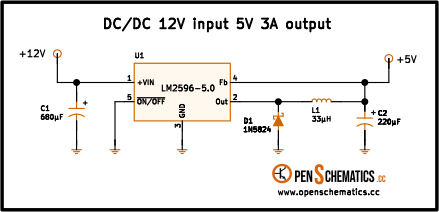
Pinout
| Pin | Function |
|---|---|
| VIN | Unregulated supply input. Feeds the internal power switch directly. |
| Output | Switched output of the internal transistor. Delivers the pulse train that drives the external L-C-D stage. |
| GND | Common terminal of the circuit and reference for the output voltage. |
| Feedback | Regulation-loop input. Compares the sensed voltage against the internal reference and trims the duty cycle. In the fixed-voltage versions it ties to the output through an internal divider. |
| ON/OFF | Active-low enable input. A low level runs the regulator; a high level shuts it down and drops the current to standby. |
LM2596
The LM2596 is a step-down (“buck”) switching regulator that replaces linear regulators when the input-to-output differential makes burning the excess power as heat impractical. It delivers up to 3 A with very few external parts.
It comes in an adjustable variant and in several fixed-voltage variants. This design uses the 5 V one to bring a 12 V input down to the 5 V that logic typically needs.
How the circuit works
The buck converter principle is to store energy in an inductor while the switch is closed and hand it back to the load when it opens. The LM2596 opens and closes its internal switch 150,000 times per second and adjusts the time it stays closed — the duty cycle — from what it reads on the Feedback pin: if the output sags, it stretches the on-time; if it rises, it shortens it.
While the switch is on, the input voltage reaches inductor L1 (33 µH), which charges with a current that ramps up while it simultaneously feeds the load and tops up output capacitor C2 (220 µF). Diode D1 (1N5824, a 5 A Schottky) is reverse biased and does not conduct.
When the switch opens, the inductor will not allow an abrupt change in current and holds its own by pushing the output node upward: the Schottky becomes forward biased and closes the loop to ground — hence the name freewheeling diode. The inductor current now ramps down while still feeding the load.
Input capacitor C1 (680 µF) is the one that absorbs the current spikes the supply cannot deliver while the switch is on: every cycle, the regulator pulls the load current (and some more) in a burst through the VIN pin, and without that reservoir the ripple on the input would be unacceptable.
In the fixed version, the Feedback pin connects straight to the output: the divider that sets the reference is already built in. And the ON/OFF pin is tied to ground so the regulator stays always on — if you need to shut it down from a microcontroller, just pull that pin high.
Application design
With the fixed version, the only parts to choose are the inductor, the diode, the output capacitor and the input capacitor. The datasheet provides tables and nomographs for all four; here it is enough to grasp the ideas behind each one.
Inductor. The only part that deserves a bit of calculation. It is sized by picking the current ripple we want through it — a common rule of thumb is around 30 % of the output current. Ignoring the switch and diode drops, the duty cycle is approximated by:
And from the voltage across the inductor during the on-time it follows directly:
With , , , (30 % of 3 A) and that gives about 22 µH; the closest standard value above it, 33 µH, is exactly what the datasheet nomograph recommends.
Schottky diode. It must be a Schottky (low forward drop and essentially no reverse recovery) and rated for the full output current. The 1N5824 (5 A, 40 V) has plenty of margin.
Output capacitor. It sets the voltage ripple and stabilises the loop. What matters at this frequency is not capacitance but ESR: a 220 µF low-ESR part keeps the ripple down to a few tens of millivolts.
Input capacitor. It absorbs the current spikes the supply cannot deliver during the switch on-time. The 680 µF used here has plenty of margin.
Other applications
The LM2596 covers virtually any step-down job where the differential is too big for a linear regulator. Some typical uses:
- On-board step-down (POL) supplies. Bringing a 12 V or 24 V bus down to the 3.3 V or 5 V logic needs, without the heat of a linear regulator.
- Simple battery chargers. In adjustable mode, the output is set to the desired float voltage; the built-in current limit adds a basic layer of protection.
- Pre-regulator ahead of an LDO. The buck drops the voltage efficiently to a couple of volts above the final value; a downstream LDO cleans up the switching ripple for sensitive stages.
- Local on-board regulation. Feeding specific subsystems from a higher main rail, avoiding routing the final voltage across the entire board.
- Drop-in for hot linear regulators. A direct replacement when a 78xx or similar falls short on dissipation, especially at 1 A or more of load.
References and further reading
- PDFLM2596 datasheet
This is the main source this article was created from.
- WEB
- WEB