
Linear isolation amplifier for an isolated analog input
LOC110
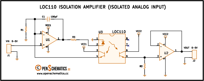
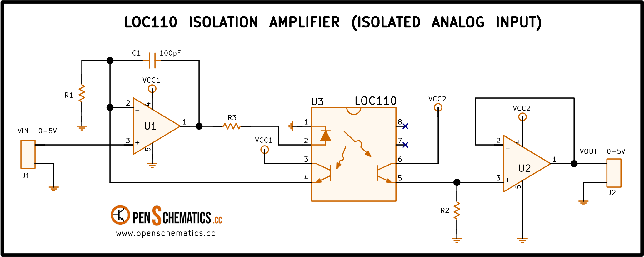
Pinout
| Pin | Function |
|---|---|
| Pins 1 and 2 | Infrared LED of the optocoupler, the light source that carries the signal. |
| Pins 3 and 4 | Input-side reference photosensor, which picks up part of the LED light. |
| Pins 5 and 6 | Output-side photosensor, galvanically isolated from the input side. |
| Pins 7 and 8 | No internal connection. |
LOC110
The LOC110 is a linear optocoupler: an infrared LED that shines equally on two photodetectors, one on the same side as the LED and one across the isolation barrier. That symmetry is its whole reason to exist.
An ordinary optocoupler is fine for logic levels but not for an analog signal: the relationship between LED current and emitted light is not linear, and it also drifts with temperature and with the ageing of the LED itself. The LOC110 does not try to correct that flaw — it measures it. Both photosensors, the input one and the output one, are identical. Op-amp U1 controls the LED current so that the response of the input photosensor is proportional to the input voltage; and since the other photosensor is identical and receives the same light, the output ends up being a copy of that same voltage, only galvanically isolated.
It is the compact alternative to an isolation transformer, and unlike a transformer it couples DC signals just as well as AC ones.
How the circuit works
The input side is a closed loop that controls the light. enters through the non-inverting input of U1, while the inverting one sees the voltage the input photosensor develops across R1. If that voltage sits below , U1 drives its output up and pushes more current through the LED (via R3); the LED shines brighter, the photosensor conducts more and the voltage across R1 rises. The loop settles when both inputs of U1 are at the same level, and from then on the voltage across R1 tracks instantly.
Here lies the key: the loop does not set an LED current, it sets a light level. It does not matter whether the LED degrades, heats up or differs from another sample — U1 will inject whatever current is needed to keep the photosensor seeing the same thing. The LED non-linearity stays inside the loop and drops out of the result.
The output side only reads. The second photosensor receives the same light and gives a current that faithfully tracks the first one; R2 turns it back into a voltage and U2, wired as a follower, copies it to connector J2 without loading the node. This side has its own ground and its own supply (VCC2): the only link to the input is the beam of light.
That leaves C1, the 100 pF capacitor between U1’s output and its inverting input, which limits the bandwidth of the input amplifier: the higher the frequency, the lower its impedance and the more feedback it returns, so U1’s gain falls off and the circuit stops responding to fast signals. That is the point, because the delay of the optical path would otherwise make the loop oscillate: speed traded for stability.
Application design
Both photosensors in the LOC110 are identical and receive the same light, so it is safe to assume the same current flows through both — call it . That reduces the whole circuit to two ideas already seen:
- The input loop forces the voltage across R1 to equal the input voltage: .
- The output is that same current across R2: .
Since the current is the same in both expressions, it cancels when you divide one by the other, and what is left is the gain of the isolation amplifier:
In other words: the gain depends only on the ratio of two resistors, exactly as in a conventional op-amp stage. Neither the LED, nor temperature, nor the tolerances of the optocoupler appear anywhere. This circuit wants 5 V out for every 5 V in, so it is enough to make .
The absolute value of those resistors is set by the current asked of the LED at the top of the range. With R1 at a few tens of kilohms, 5 V full scale works out to an LED current of about 10 mA, which any op-amp sources comfortably; R3 is then chosen so U1’s output does not have to swing too close to its supply rail.
Two practical notes: the two currents are not exactly equal from part to part, so precision measurements are better served by making R2 adjustable and calibrating the gain once assembled; and with the photosensors reverse biased, as in this circuit, it reaches around 200 kHz of bandwidth with linearity comparable to an 8-bit converter. If accuracy matters more than speed, there is a variant of this circuit in photovoltaic mode, which trades bandwidth for much better linearity and lower drift.
Other applications
The LOC110 shows up wherever a signal has to cross an isolation barrier without losing its shape — power-supply feedback, medical instrumentation or industrial control:
- Feedback in isolated switching supplies. Sensing the secondary-side voltage and feeding it back to the primary-side controller without breaking the supply’s isolation.
- Medical instrumentation. ECG or EEG equipment, where the electrodes attached to the patient must sit behind a high-voltage barrier separating them from the rest of the machine.
- Industrial control. Temperature sensors and transmitters located far from the controller or near high voltage; the isolation protects both the equipment and whoever operates it.
- Telecommunications. Coupling the signal between the telephone line and the equipment electronics, a classic case in modems.
- Replacing signal transformers. Where a bulky transformer used to be needed, with the added benefit of coupling the DC component too.
References and further reading
- WEBApplication note AN-107 — Linear Optocouplers (LOC series)
This is the main source this article was created from.
- WEB